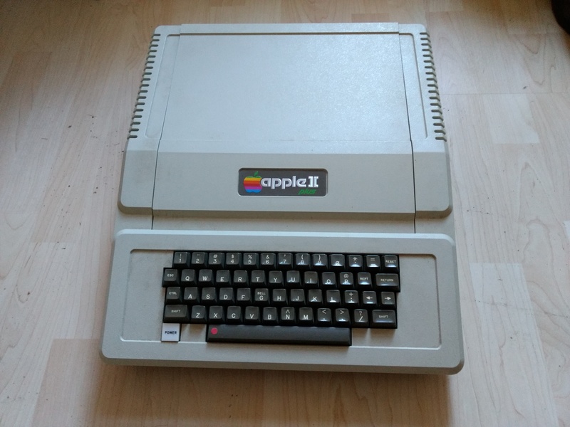
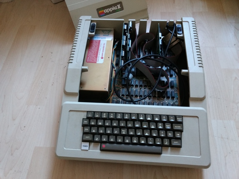
My first Personal Computer, one I owned, rather than one I used, was an Apple II Plus, which I bought from Pete and Pam Computers around 1980. They had recently started in business importing Apple computers from the US, as this was before the Apple II Europlus. The switched mode power supply, although it had a jumper setting for 240 volt power, used a bridge rectifier which, after much use, finally expired – possibly under-rated for the job, and I had to replace it with a higher rated, but bulkier one, where the pins only just reached the circuit board, so I had to re-solder it from time to time. Apart from this the quality of the system was very impressive. Equally impressive was the documentation.
Having good documentation was essential for fixing the power supply, but particularly in those early days of Personal Computing, the feeling that this was not some incomprehensible ‘black box’, where the owner was merely a ‘user’, but a system created by fellow enthusiasts who wanted to share their knowledge.
Much of the openness of the original Apple II is probably down to Steve Wozniak, who later helped to fund the Electronic Frontier Foundation, and is still involved the groups working to improve technological eduction.
An example of this is the way the Apple II read programs and data from cassette tapes.
The Cassette Tape Interface
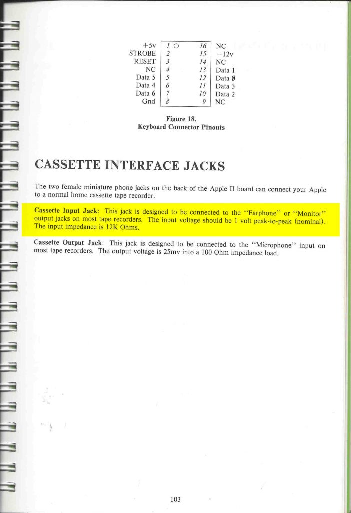
The Apple II read from cassette tape through a combination of hardware and software, each relatively simple. There were a pair of jacks on the back of the case to plug in a normal domestic cassette recorder (which were quite common and cheap in those days).
The data on the tape is stored as an audio signal, the ones and zeros of binary data having been converted to sound through Frequency Shift Keying.
The cassette recorder output can be plugged into a socket on the rear of the Apple II, which connects it to the circuit shown on page 114 of the Reference Manual.
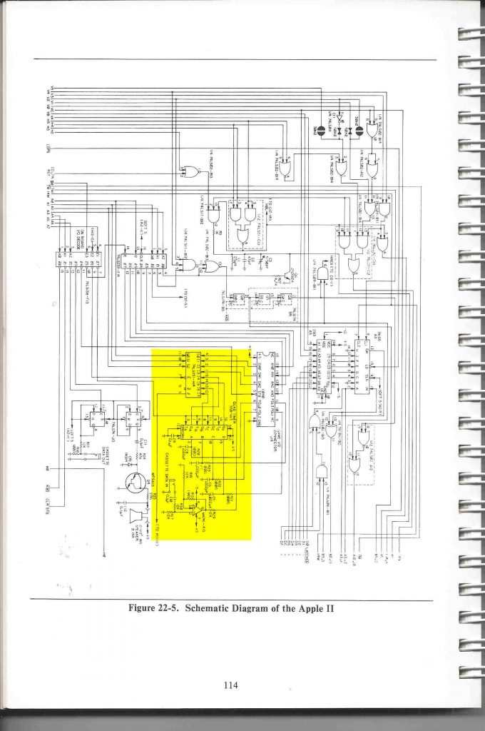
The operation of the circuit is described on page 22 of the Reference Manual.
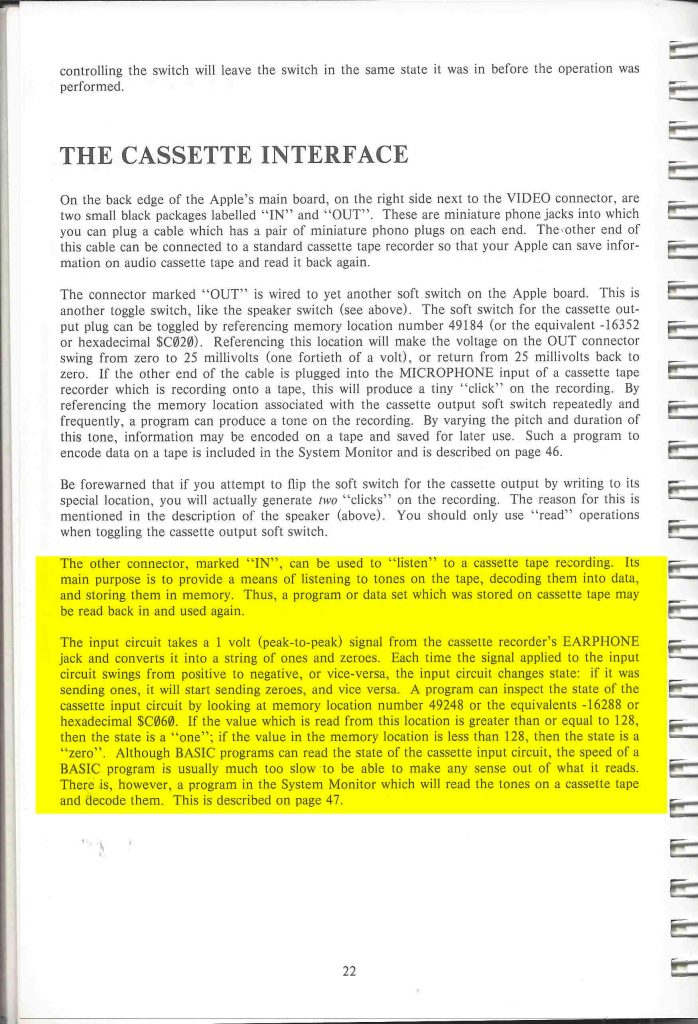
The Op Amp at K12 is used as a Zero Crossing Detector, ultimately resulting in the memory at $C000 being above or below 128, depending on whether there is a signal from the tape or not.
A binary “1” is a 1 KHz tone, i.e.the memory being examined will switch from about to below 128 a thousand times a second, whereas a binary “0” is encoded as a 2 KHz tone, and translating from the Most Significant Bit of the memory at $C000 is done in software.
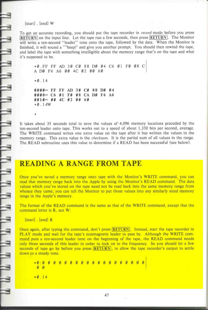
This is described in a section of the System Reference which describes the System Monitor, a low level, command line interface to the system, which provided the “R” command to read from the tape into computer memory.
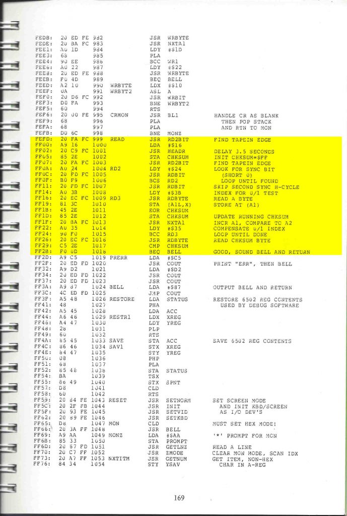
The Assembler code for the 6502 instructions which implement the Reading A Range From Tape can be found on page 169 of the System Reference
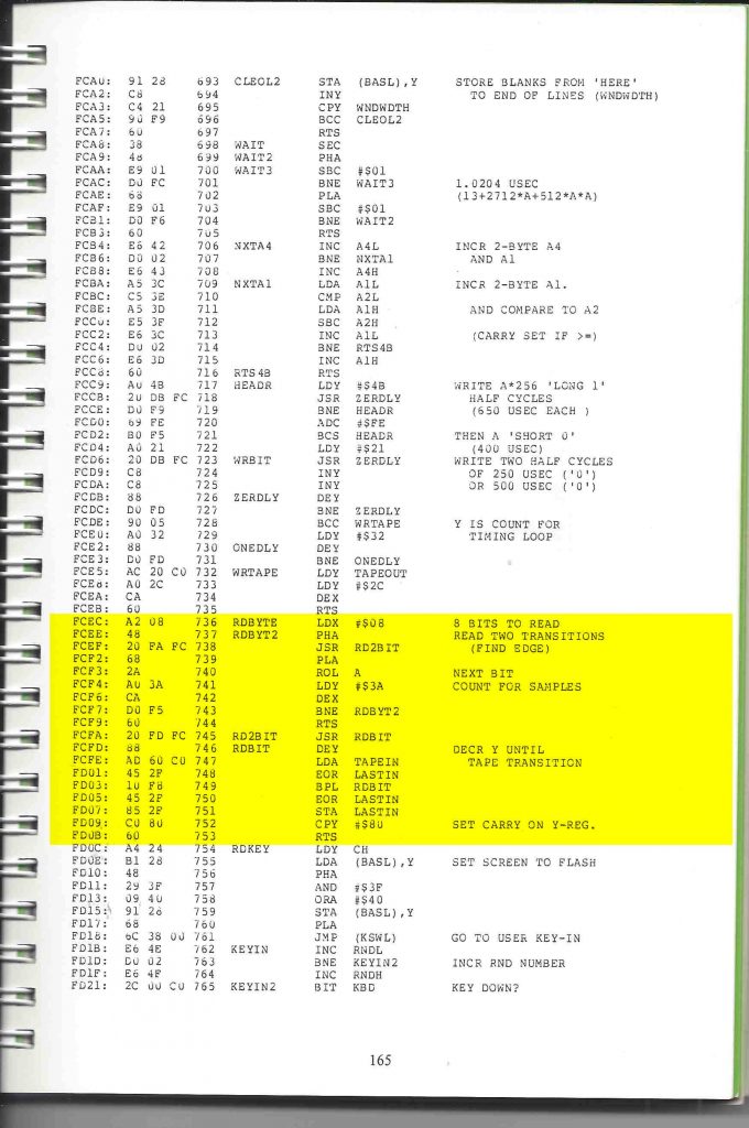
The subroutines it calls (JSR is a 6502 machine code instruction which stands for Jump to Subroutine), can be found on page 165.
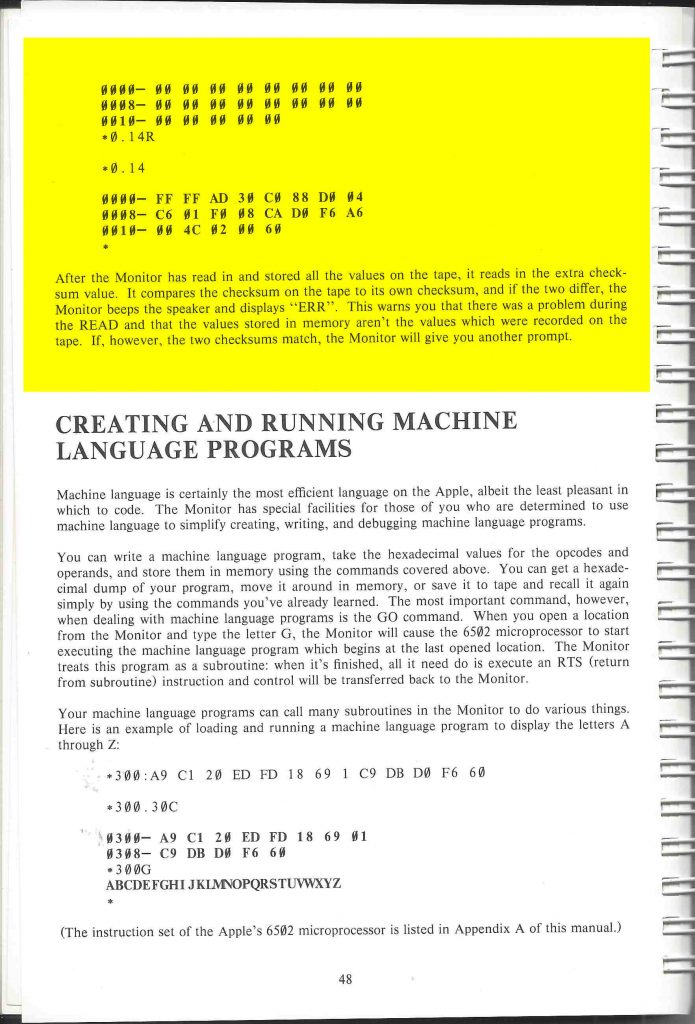
The Reference Manual even contains a guide to the 6502 machine code instruction set, explaining, for example that PHA means Push the Accumulator onto the Stack. This allowed the owner (with some patience and thought) to work out exactly how a set of noises on a tape can end up as data in computer memory.
Implications of the cassette tape interface.
If you listen to a musical instrument playing A , which is the note that orchestras are tuned to, the sound waves are hitting your ear at 440Hz, that is, your eardrum is moving backwards and forwards 440 times a second. If cassette circuit was picking up the same changes they would be less than half the 1000 times a second of the lower note. The software would be sitting, looping round waiting for the next change from in to out for more than twice the time it does to decode the signal from the tape.
The 6502 processor used by the Apple II was clocked at 1Mhz. Although not directly comparable, the processor in a humble Raspberry Pi Zero is clocked at 1Ghz – one thousand times as fast.
The Apple II cost around £1000 – a substantial sum in 1980, and came with full manuals and detailed description of exactly now everything worked. The Pi Zero, with power supply, case and SD card costs under £50, but comes with a sheet of paper, mostly about the warranty. Although very open in some respects, while the source code for the Apple II monitor was provided in the manuals, the Raspberry Pi relies on closed source binary blobs for it’s firmware, which are a barrier to the ability to understand the whole system from physics to computer science.